
August 5, 2025Operationally Efficient Hotel WellnessHospitality pools & Wellness
The architectural structure of a wellness space must provide independent circulation loops for guests and staff. Service corridors, storage niches, service entrances to treatment rooms, and technical areas are designed so that linen logistics, cleaning, and replenishment do not intersect with guest routes.
The minimum width of BOH corridors (Back of House – the operational area hidden from guests) is determined by calculated usage intensity and typically should not be less than 1200 mm. Vertical connections (service lifts and stairs) are integrated into the overall hotel scheme at the concept stage. This reduces hidden labor costs, minimizes visual noise, and increases privacy.
Wellness operates as a logistical system. Clean and dirty linen, bathrobes, towels, consumables, and cleaning supplies must move along a clearly organized route: storage → preparation zone → treatment room / hall → return → laundry.
Storage volume is calculated based on turnover frequency (on average 3–5 textile sets per shift). Intermediate textile storage areas are provided near clusters of treatment rooms. Wet rooms and storage areas are equipped with forced ventilation and moisture-resistant finishes. This organization reduces staff travel distance and eliminates bottlenecks during peak hours.
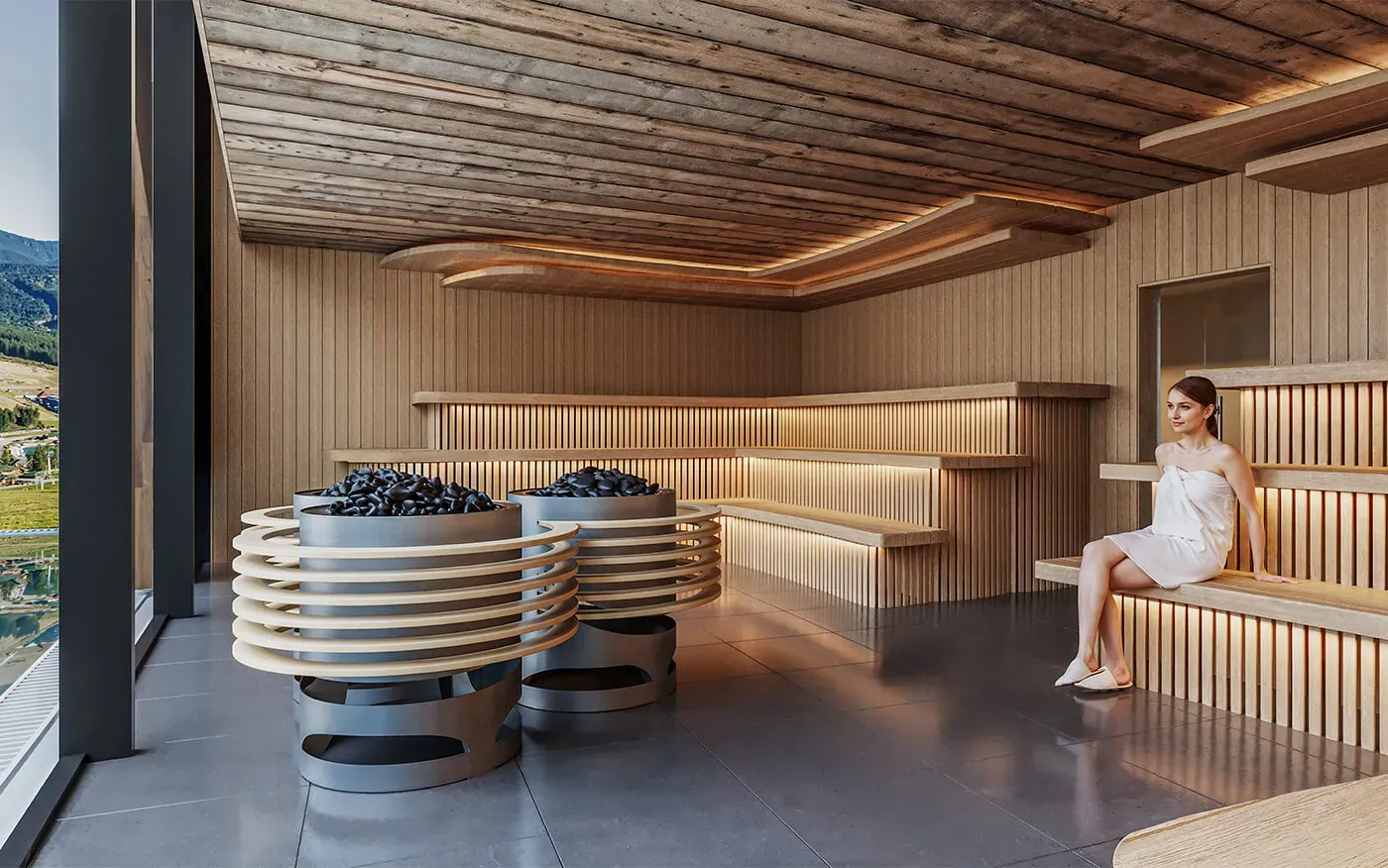
The hydrothermal complex — sauna, hammam, cold plunge pools, warm pools — is a core element of the operational model. Engineering integration of the wellness zone must begin not at the detailed design stage, but at the Concept stage, simultaneously with spatial planning and functional modeling.
In our projects, all technical rooms for water treatment systems, disinfection, heat exchange units, ventilation/dehumidification/heating/air-conditioning systems, steam generators, chillers, and related infrastructure are fixed in the plans from the earliest stages. This is fundamental: technical feasibility of connections and availability of required capacities determine not only CAPEX, but also future OPEX and operational reliability.

At the concept stage, engineering units are defined as mandatory functional blocks with:
Otherwise, a typical mistake occurs: the wellness area is visually “assembled,” and equipment is “placed somewhere later.” This results in long service routes, conflicts with architectural elements, shaft coordination issues, and expensive compensatory solutions (oversized pumps, additional automation, oversized piping and ductwork).
Each engineering node at the concept stage is checked for technical feasibility of connection:
We separately verify the feasibility of remote installation: many solutions may theoretically function over long distances, but in practice this leads to larger pipe diameters, more expensive fittings, control instability, and reduced efficiency.
One of the most common mistakes is placing technical rooms too far from the thermal zone or pool area. This automatically leads to:
Operationally, this directly increases OPEX through higher electricity consumption, additional thermal losses, increased equipment load, and more frequent maintenance. The principle of “short engineering connections” or a rational distributed system (local nodes near consumption groups + central energy center) significantly improves efficiency. Engineering shafts and routing are designed simultaneously with architecture, not afterward.
The location of the wellness zone within the hotel structure determines flow behavior and commercial efficiency. The entire guest journey is analyzed: distance from guest rooms, vertical connections, access to fitness and F&B areas. Acoustic insulation from guest rooms should not be lower than Rw 55 dB. Distance to restaurant areas influences secondary revenue. Incorrect positioning leads either to underutilization or infrastructure overload.
Optimization is achieved through standardized treatment room modules. A typical massage room is designed at 10–14 m²; wet-treatment rooms at 14–18 m² with integrated shower units.
Engineering systems (water supply, drainage, ventilation, electrical) follow a repeatable scheme. Ventilation ensures 4–6 air changes per hour, and acoustic insulation not less than 50 dB. Standardization reduces construction costs, simplifies maintenance, and increases scheduling flexibility.
Wellness areas fall into the category of high-humidity, high-temperature-variation spaces. Structural solutions include multi-layer waterproofing, floor slopes of at least 1.5–2%, drainage systems with inspection access, and clear separation of “wet” and “dry” building envelopes. Errors in floor levels or vapor barriers lead to leakage and expensive repairs. Therefore, connection details, vapor barriers, and ventilation shafts must be fully developed at the working documentation stage.
Indoor climate parameters vary by scenario:
When forming the thermal zone, it is critical not to rely on a “standard sauna set,” but on analysis of the target audience. Temperature preferences, humidity tolerance, duration of stay, and cultural habits differ significantly among families, wellness tourists, sports groups, or premium guests. Proportions of sauna types must reflect actual demand.
Wellness combines zones of different acoustic intensity — quiet relaxation, social interaction, fitness. Buffer spaces, acoustic partitions, and high-insulation doors are applied. Noise levels in relaxation zones should not exceed 40 dB. Engineering systems are designed with integrated noise control, reducing the need for constant staff supervision.
Operationally efficient wellness allows functional transformation. Yoga rooms may also serve for seminars or meditation. This is achieved through mobile partitions, universal engineering distribution, and scenario-based lighting (DALI / DMX). Such architectural flexibility increases space utilization rates and allows adaptation to seasonal demand without reconstruction.
The planning model must incorporate financial mechanisms. Access control systems (RFID wristbands), tariff zoning, and upsell logic (VIP changing rooms, private suites) are designed simultaneously with architecture.
Capacity is calculated based on time slots and average duration of stay. In this way, the space becomes a revenue management tool rather than merely a service environment.